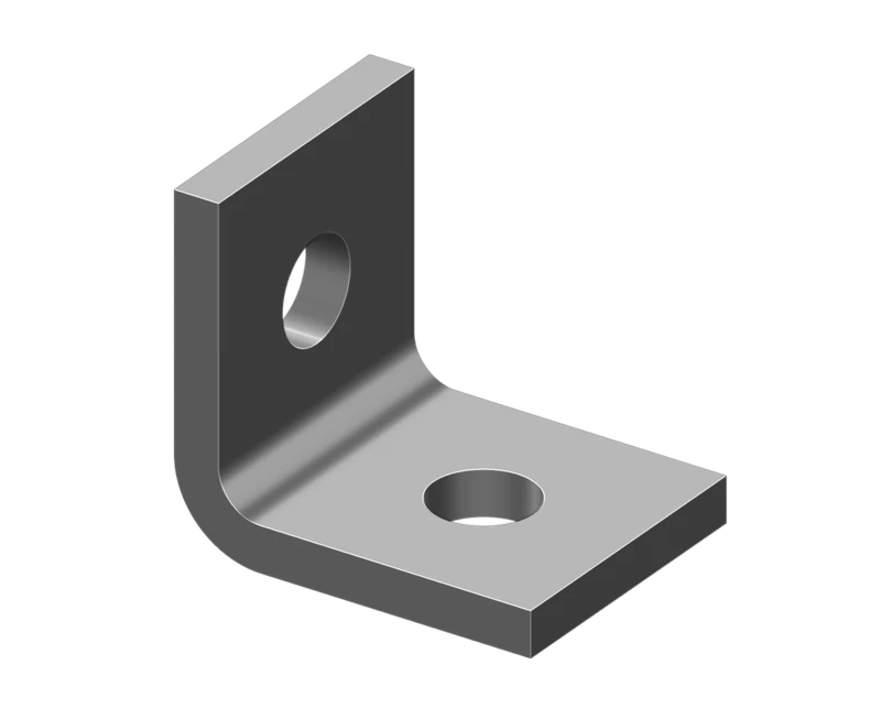
Neutral 3D catalog-reference illustration, not a product photograph. Finish selection changes the inquiry option, not the illustration.
View dimensions & full-size drawing90° ANGLE FITTING · CATALOG REFERENCE
P1026 — 2-Hole 90° Angle Fitting
By Alex · Last reviewed · Correction? Tell us.
A two-hole angle fitting for identifying a connection and preparing a quote request.
- Reference size
- 2 × 1-7/8 in. (50.8 × 47.6 mm)
- Holes
- 2 × 9/16 in. (14.3 mm), one per leg
- Our base steel
- About 0.23 in. (5.8 mm), before coating
Steel grade confirmed at quotation. Catalog geometry is a reference, not a production drawing for our supply.
Electro-galvanized (EG) — ASTM B633 Type III SC1
Hot-dip galvanized (HDG) — ASTM A123 / A153
Plain — uncoated steel
Stainless — 304 or 316, grade confirmed at quotation
Powder coating — to a RAL color you specify
Nuts and bolts are not supplied with the fitting and must be ordered separately.
Request a quote for P1026The table below describes the catalog reference part; its thickness is not our supply base-steel specification.
| Dimension | Catalog value (reference part) | Source |
|---|---|---|
| Leg A | 2 in. (50.8 mm) | Printed on the P1026 drawing, p. 94 |
| Leg B | 1-7/8 in. (47.6 mm) | Printed on the P1026 drawing, p. 94 |
| Hole count | 2, one per leg | Shown on the P1026 drawing, p. 94 |
| Width | 1-5/8 in. (41.3 mm) | Page-94 standard-dimensions note |
| Catalog reference thickness | 1/4 in. (6.4 mm) | Page-94 standard-dimensions note |
| Hole diameter | 9/16 in. (14.3 mm) | Page-94 standard-dimensions note |
More catalog details & unpublished dimensions
| Dimension | Catalog value (reference part) | Source |
|---|---|---|
| Hole center from end | 13/16 in. (20.6 mm) | Page-94 standard-dimensions note — checked against a physical sample, 2026-09-03 |
| Steel | ASTM A575 / A576 / A635 / A36 | Fittings material note, p. 85 — also meets the physical requirements of A1011 SS GR 33 |
| Bend radius | not published | Not dimensioned anywhere on p. 94. The drawing shows a rounded outer corner but gives no value, and we do not compute one. |
| Hole center to bend | not published | Not dimensioned on p. 94. Deliberately not derived from leg length minus end distance. |
Source: Unistrut® General Engineering Catalog no. 17, p. 85 and p. 94 · Verified 2026-09-03. The first three rows appear on the part illustration; the standard-dimensions note supplies width, thickness, hole diameter and end distance.
Confirm the connection, not just the number.
Identify the mating channel, hardware and project requirements in your inquiry. Nuts and bolts must be ordered separately.
No load rating is published here for P1026. A catalog reference, similar shape or trial fit does not establish the performance or approval of a proposed connection.
Use the receiving record to link a delivery to the approved order and document unresolved differences.
Reference: Unistrut® General Engineering Catalog no. 17, p. 85 and p. 94. Confirm the supplied combination against the approved drawing and order.
Catalog reference drawing
Catalog reference dimensions are shown in inches, with millimeters in parentheses. The separate supply-thickness detail shows about 0.23 in. (5.8 mm) base steel before coating; it does not change the 1/4 in. (6.4 mm) catalog model. The bend radius is illustrative and is not a specified manufacturing dimension.
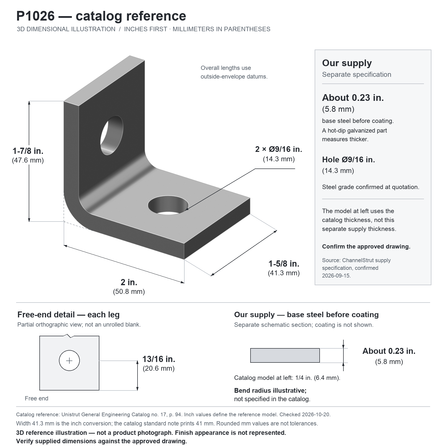
Catalog reference: Unistrut General Engineering Catalog no. 17, p. 94 · Checked 2026-10-20. Supply specification confirmed 2026-09-15. Original catalog-traced drawing (SVG).
Published candidate references
| Brand | Published cross-reference part number |
|---|---|
| B-Line | B230 [S1][S3][S4] |
| Superstrut | AB202 [S1][S3] |
| Power-Strut | PS 603 [S1][S3] |
| Haydon | A-302 [S3] |
Row note: S4 prints the Superstrut number as AB-202.
A published cross-reference number identifies a candidate substitute in a cited table. It does not transfer a load rating, steel grade, coating specification or listing.
Read the source documents and comparison limits ↗Full supply summary & reference geometry
| Dimension | Value | Source |
|---|---|---|
| Leg A | 2 in. (50.8 mm) | Unistrut® General Engineering Catalog no. 17, p. 94 — printed on the part drawing |
| Leg B | 1-7/8 in. (47.6 mm) | Unistrut® General Engineering Catalog no. 17, p. 94 — printed on the part drawing |
| Width | 1-5/8 in. (41.3 mm) | Unistrut® General Engineering Catalog no. 17, p. 94 — standard-dimensions note in the page header |
| Holes | 2, one per leg, 9/16 in. (14.3 mm) | Unistrut® General Engineering Catalog no. 17, p. 94 — printed on the part drawing and Unistrut® General Engineering Catalog no. 17, p. 94 — standard-dimensions note in the page header |
| Our base-steel thickness | About 0.23 in. (5.8 mm) base steel before coating; a hot-dip galvanized part measures thicker. Steel grade confirmed at quotation. | Our supply specification — not a catalog figure |
Candidate substitute made to order by a contract manufacturer; not an original-manufacturer part. Finishes: Plain, EG, HDG and stainless, plus powder coating on request. Documents and their availability must be confirmed at quotation.
Prepare a P1026 inquiry
Include the part, quantity, finish and destination. Note any drawing or application requirements.
We reply within one business day (Asia/Shanghai, UTC+8).
Sources & reference limits
Dimensions: Unistrut® General Engineering Catalog no. 17, pp. 85 and 94. Cross-reference labels [S1], [S3] and [S4] refer to the documents listed on the P1026 cross-reference source page.
Production lead time and commercial terms: Ordering terms. Required documents: availability and limitations.
Trademarks and who we are
Unistrut, B-Line, Superstrut, Power-Strut and Haydon and their part numbers belong to their respective owners. ChannelStrut is independent and is not affiliated with, authorized by or endorsed by them.